
Hi,
I have a query on the calculation of concrete edge failure on a beam-to-concrete wall end plate connection.
I am a civil engineer designing an end plate connection from a UC to an existing concrete wall by using Hilti Profis online tool.
In my design scenario as shown in the attached image, the connection is very close to one edge of the wall (50mm) and it is subjected to a dominant shear load (75kN) in the x-direction, which can be described as parallel to the edge. The remaining edges are set as infinite.
After I modeled this in Hilti Profis, I found there is an exceptionally high utilization of concrete edge failure/breakout. As a result, I checked the result from the generated report from Profis and I found that the load used for the concrete edge failure calculation is just divided by 2, while as per BS EN 1992-4:2018 Cl, 6.2.2.2(2) NOTE 2, it is suggested that the load could be shared by all bolts. Here is the quote of the note:
''NOTE 2 In case of groups of fasteners where only the fasteners closest to the edge are effective, the component
of the load acting perpendicular to the edge is taken up by the fasteners closest to the edge, while the components of the load acting parallel to the edge – due to reasons of equilibrium – are equally distributed to all fasteners of the group (see Figure 6.5 c))''
In other words, in my design scenario, my design load could be further reduced from 75/2 = 37.5kN to 75/8 = 9.375kN, and there is a possibility that my connection could work.
As a consequence, unless I have misunderstood anything, may I have a clarification on this difference and the methodology of the calculation in concrete edge failure in Profis, please?
Many thanks
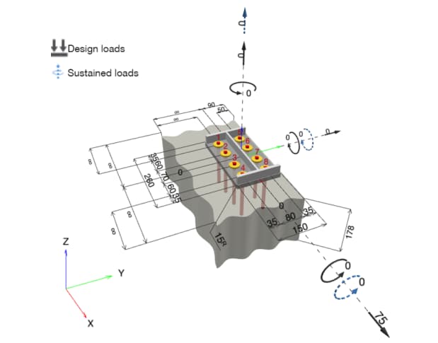
Thank you for your enquiry and the attached image regarding EC2 Part 4. Looking at the details supplied, the anchor arrangement unfortunately doesn’t comply with the criteria stipulated with EN1992 Part 4 Section 1.2 Type of fasteners and fastenings groups 5 Figure 1.2
Now where Profis Engineering has produced a calculation is the based upon the ‘Filled hole ‘ basis as an extension of the design code to allow for non-conforming arrangements as indicated on your image. You will have been prompted to select this option to enable the software to proceed and perform the calculation.
The software will have assessed your input, recognised the arrangement of fasteners is beyond the ‘regular’ pattern, therefore, follows an assumption that homogeneous shear distribution is not valid.
Shear resistance is calculated using either of the following EC2 Part 4 or ETAG or FIB with gap filling as a requirement. As for the specific methodology we made that easier for you as the software automatically prompts depending upon your inputs into the software.
Additionally, layouts beyond 3 x 3 and other irregular patterns follow the SOFA & ETAG or SOFA & FIB design approach where only the first row contributes to the concrete edge breakout resistance with no shear transferred to the back rows .