

When using the PROFIS software what considerations are used for welded joints.
Connections between different steel elements in PROFIS Engineering are done with the assumption that welds are being used.
The user is able define the material properties of the weld element, as well as geometry and dimensions. Fillet welds and full penetration butt welds can be modelled.
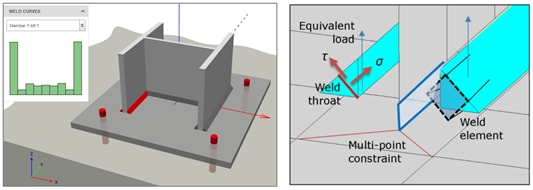
Figure 1: PROFIS Engineering fillet weld models [1]
In PROFIS Engineering CBFEM, a multi-point constraint automatically generated to model the welds, connecting the steel elements (shell elements).
As the behavior of steel is non-linear, the CBFEM modelling has the advantage of allowing for re-distribution of stress in the welds and avoiding stress peaks, as illustrated in Figure 2. The weld resistance is determined by the directional method in EN1993-1-8.
Example of an outer flange fillet weld under uniaxial bending
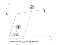
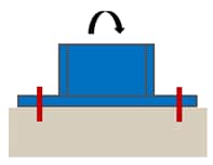
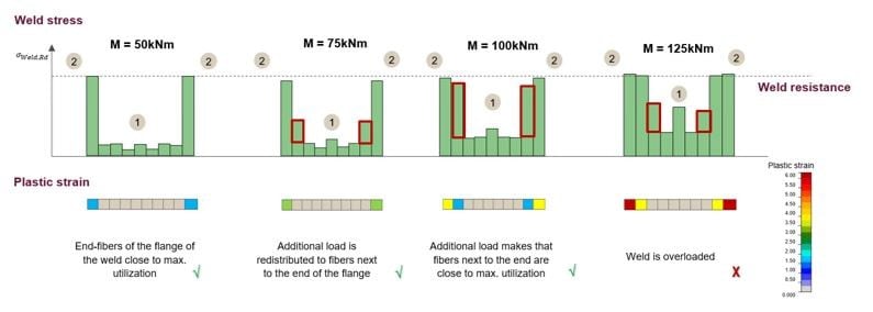
Figure 2: Schematic illustration of non-linear behavior of welds
[1] Hilti Cooperation, Advance Base Plate Technical Background, 2019