

Design of the longitudinal Shear Strength of Concrete-to-concrete Interfaces acc. to EOTA TR06
This is part 2 of our previous article which considered a comprehensive look at the topic of concrete overlay. Examining the current dimension regulation for overlay and dealing with the individual load-bearing components that describe the load-bearing resistance of the interface of concrete overlay. If you are yet to read part 1 please take a look now.
4 Design of the shear joint according to EOTA TR 066
4.1.1.1 Impacts - Static and quasi-static action- External forces
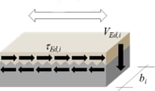
To determine the acting shear stress, the applied external shear force VEd,i is converted by the following equation into a shear stress τEd,i acting parallel to the interface in a given section i:
 [N/mm2]
Figure 11 Conversion of the external shear force VEd,i into a shear stress τEd,i acting in parallel in the interface of the composite joint
β = ratio between the longitudinal force in the new concrete and the total longitudinal force in either the compression or tension zone, for the section under consideration, see Figure 12.
VEd,i = acting external shear force
bi = width of the zone under consideration
z = Lever arm of the internal forces
These areas or zones of length li can be defined based on the shear stress distribution due to external loading (shear force distribution), whereby the maximum shear stress within the zone is decisive. The ratio of the longitudinal forces related to the total longitudinal force b depends on the height of the new concrete layer related to the height of the concrete compression zone (positive bending moment, see Figure 12).
Where 𝑥 is the height of the concrete compression area, A𝑠,N is the cross- sectional area of the reinforcement in the new concrete layer, A𝑠,E is the cross- sectional area of the reinforcement in the existing concrete, hN is the height of the new concrete layer and hE is the height of the existing concrete ("old").
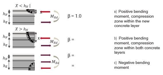
Figure 12 Determination of the ratio of the longitudinal force in the new concrete to the total longitudinal force (b) considering different boundary conditions
4.1.1.2 Forced forces
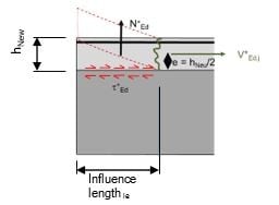
Figure 13 Lifting forces due to shrinkage according to EOTA TR066 [2], schematic
EOTA TR 066 [2] also considers constraint forces at the edge of the concrete layer due to shrinkage under static and quasi- static actions. This generates shear stresses parallel to the bond joint t*Ed and uplift forces N*Ed,j (Fig. 13). These uplift forces are considered within a certain influence length le along the edge area depending on the surface roughness and the height of the new concrete layer.
These must be smaller than the tensile resistance NRd of the shear connector taking into account the governing failure mode. The higher the new concrete layer and the rougher the concrete surface, the greater the length le that must be taken into account.
It should be noted that in EOTA TR 066 [2], the constraint forces are not superimposed with the acting forces from external loading, as the required verification is carried out separately by a verification against external loading and a verification against constraint forces. For the verification against constraint forces, either the shear stress from the constraint forces or the applied shear stress from external actions in the interface is taken into account, whereby the maximum value of the applied shear stress is decisive:(tEd=max.(tEd,i; t*Ed)).
4.1.2 Fatigue action
The fatigue resistance of materials or components is generally determined experimentally with cyclic loading tests in which a pure fatigue action is applied without static actions. In cases where actions consist of a combination of fatigue and static actions, it is necessary to take this into account as it has an influence on the fatigue strength of the composite joint. Consequently, EOTA TR 066 [2] categorises the fatigue action that generates a cyclic load in the composite joint by 3 situations (Figure 14):
- Situation 1 The acting cyclic shear stress ΔtEd is based on a fatigue action without static component (puls. action)).The lower cyclic loading takes the value zero (ΔtEd ,min=0).
- Situation 2 The applied cyclic shear stress ΔtEd is based on static action (pulsating action) and fatigue action. The lower cycl. loading is greater than zero ((ΔtEd ,min>0).
- Situation 3 The acting cyclic shear stress ΔtEd follows with changing signs.
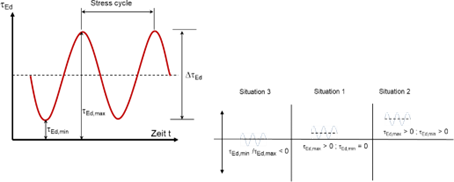
Figure 14 Designation and categorisation of cyclic action according to EOTA TR 066
4.1.3 Seismic action
For the design under seismic action, the interface is designed for the maximum load that results from the load combinations with earthquake loads VEd,i,seis according to EN 1998-1:2004 [10] in the ultimate limit state. Additional boundary conditions with regard to design as well as application-specific boundary conditions (slab, wall, beam, frame structure) of the reinforcement measure must be taken into account when determining the earthquake load acting on the reinforced interface.
4.2.1 Resistance of the shear joint - Static, quasi-static resistance
Two application conditions are defined for the calculation of the shear strength of the interface Rd
4.2.1.1 Shear capacity of the shear joint without shear connectors (rigid composite)
Application condition 1 applies to rigid bond without subsequently installed shear connectors, where a good bond can be assumed and no tensile stresses occur perpendicular to the shear joint. In this case, the design of the shear resistance of the interface is carried out via the adhesive bond (No.1 in Fig. 15) and friction due to external normal stresses (No.2 in Fig. 15) without considering shear connectors. The corresponding coefficients depend on the roughness of the joint and are given in EOTA TR 066 [2].
The shear strength is limited by the concrete compression strut (No. 3 in Fig.15). The maximum shear strength of the bonded joint is approximately 30% of the design value of the concrete's cylindrical compressive strength. 
Figure 15 Application condition I: Shear capacity of the composite joint without shear connector (rigid composite)
If the condition tEd ≤ tRd is fulfilled, post-installed shear connectors are only required at the edge due to shrinkage (cf. chapter 4.1.1.2). If the condition tEd ≤tRd is not fulfilled, post-installed shear connectors are required in the edge area along the interface.
4.2.1.2 Shear capacity of the interface with post-installed shear connector (reinforced interface)
Application condition 2 applies to non-rigid bond where relative displacement is allowed in the interface and post-installed shear connectors are used. Consequently, the design of the shear capacity of the interface includes the mechanisms of interlock (No. 1 in Fig. 16), friction (No. 2 in Fig. 16) and dowel action (No. 3 in Fig.16).
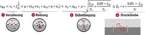
Figure 16 Application condition II: Shear strength of the reinforced interface according to EOTA TR 066 [2].
Mechanical interlock not adhesion is described by the expression "cr∙fck1/3" in the case of an interface with shear connectors and takes into account the concrete compressive strength and the surface roughness. For a reinforced composite joint, the coefficient cr takes values between 0 and 0.2. Note that compared to application condition 1, the bond resistance ca is replaced by a coefficient for mechanical interlock cr .
With increasing relative displacement of the concrete layers, the concrete layers want to separate further. The post-installed shear connectors counteract this separation and are subjected to tensile stress, causing compressive forces to develop between the surfaces, resulting in friction. In addition, the compressive forces can also be caused by external forces, which are taken into account by σN. However, the post-installed shear connectors can only be loaded up to the point where they fail in tension. The failure mode with the lowest resistance values determines the steel stress σS (Fig. 17).
The coefficient αk1 considers the percentage of the tensile force acting on the shear connector. For smooth surfaces αk1= 0. The dowel effect is caused by the relative displacement of both concrete layers. Under these conditions and depending on the value of the relative displacement, the shear connectors are subjected to shear stresses (in addition to tensile stresses due to friction) and bending stresses. As the load increases, the concrete near the surface within the interface is damaged so that the resultant of the resistance is redistributed deeper into the concrete. This increases the eccentricity between the shear force and the resultant compression at the shear connector, resulting in bending stresses in the shear connector. The factor αk2 takes this into account as the product-specific bending load capacity of the shear connector.
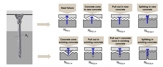
Figure 17 Specific resistance of the shear connector σs under tension depending on all possible failure modes
4.2.2 Fatigue resistance
The determination of the fatigue strength of the shear joint according to EOTA TR 066 [2] is based on several conditions. A fatigue proof is only possible if the surface is classified as very rough (Rt≥ 3.0mm), the new concrete layer has a concrete strength class of at least C40/50, while the existing concrete layer corresponds at least to concrete strength class C30/37.
If these boundary conditions are fulfilled, the shear resistance under fatigue loading can be determined by multiplying the resistance under static loading with a reduction factor ηsc and additional mathematical expressions depending on the classification of the fatigue loading, see section 4.1.2. The following example applies to the case of a pure fatigue loading (cf. fig. 4.1.2).
ΔtRd= ηsc ∙tRd resp. Δt Ed≤ ηsc ∙tRd
For situations in which a fatigue-relevant action is superimposed with a static action, the reduction is carried out according to the Goodman diagram given in EOTA TR 066 [2]. The Goodman diagram takes into account the influence of a static load on the fatigue strength. Further details can be found in [2].
4.2.3 Seismic resistance
The determination of the seismic resistance of the composite joint is based on several boundary conditions. Unreinforced interface under seismic action are not covered by EOTA TR 066 [2], furthermore a very smooth surface is not allowed according to [2]. The design check of the post-installed shear connectors must be carried out depending on the seismicity and the significance class of the structure, see EN 1992-4 [11].
In addition, a relationship must be established between the governing failure mode and the desired behavior of the interface (ductile failure modes vs. brittle failure modes). The shear resistance under static action is described by the same parameters (but with different values) as under quasi-static action. In addition, the load-bearing component from cohesion/interlocking is neglected and the total shear resistance of the joint is further reduced by a product- dependent factor αseis. This factor is specified in the product-related ETA. Further information on earthquake resistance can be found in [2].
5 A key parameter influencing the shear capacity of the composite joint: the roughness depth Rt
Figure 18a shows the shear resistance of a reinforced shear joint, calculated according to EOTA TR 066 [2], as a function of the classified surface roughness or roughness depth. The monolithic connection of the two concrete layers is executed with the Hilti post-installed shear connector HCC-B in combination with the Hilti injection system HIT-RE 500 V4.
The injection system and the shear connector are carrying the required assessment documents (ETA). Changing the joint classification from "smooth" to "rough" approximately doubles the shear resistance of the composite joint (0.21 N/mm² to 0.41 N/mm²). For the joint classification "very rough", the calculated shear resistance of the composite joint is more than four times the original shear resistance (very smooth).
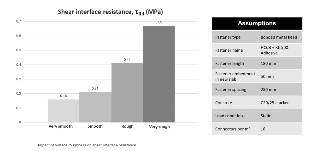
a) Shear resistance in the composite joint
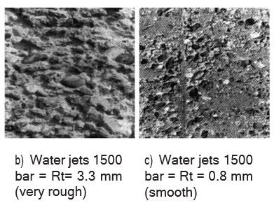
Figure 18 Shear resistance of the reinforced composite joint as a function of surface roughness and different roughness depths with identical roughening methods (water jets)
Furthermore, the verification of certain impacts requires a certain surface roughness or roughness depths. Unfortunately, the specification of the machining method is not necessarily sufficient to guarantee the required roughness depth. Figure 18a and 18b show the results in terms of measured roughness depth for identical roughening methods. Consequently, it can be said that not the method but the roughness depth Rt should be specified as the decisive parameter in the specification.
6 Practical design tips: the main differences between EN 1992-1-1 and EOTA TR 066
Not all post-installed shear connectors can be used for all edge conditions, see Figure 8. Selecting the right product may be considered as difficult. The easiest way to select the right product is to use the Hilti design software Hilti PROFIS Engineering in combination with the concrete overlay module which is available in the free standard as well as premium version.
In this software, the individual design requirements can be brought into the right context with the design requirements according to EOTA TR 066 [2] and the technically correct products. Furthermore, PROFIS Engineering offers the following additional advantages for the design of concrete overlay according to EOTA TR 066 [2]:
- PROFIS Engineering automatically optimises your results. You decide whether you want to optimize your project with regard to the minimum number of post-installed shear connectors or their minimum embedment depth.
- PROFIS Engineering takes into account static actions, fatigue actions and seismic actions in accordance with EOTA TR 066 [2].
- PROFIS Engineering provides a clear and comprehensible design report and information on the position of the post-installed shear connectors in tabular form.


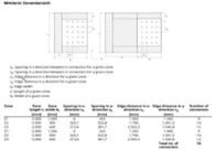
a) PROFIS Engineering, overlay Module b) Design report (extract)
Figure 19 Implementation of EOTA TR 066 [2] in PROFIS Engineering
While EN 1992-1-1 (EC2) [1] only considers cohesion, the external stresses and friction, the new EOTA TR 066 [2] also considers the dowel effect of the post- installed shear connectors.
This is necessary because in case of a relative displacement of the concrete layers, the stresses from both loading directions are superimposed in the shear connector and thus the usable axial tensile force is considerably reduced. This behavior depends on the product.
Furthermore, EN 1992-1-1 (EC2) [1] assumes a sufficiently anchored shear reinforcement, as it is known from semi-precast concrete elements, and for this reason steel yielding is considered as the decisive failure mode. In contrast, EOTA TR 066 [2] considers the individual failure modes of post-installed shear connectors. Consequently, the steel stress σs of the shear connector calculated from the design resistance under tension is used instead of the yield strength when applying the shear verification. The design resistance under tension is equal to the decisive resistance taking into account all possible failure types determined according to DIN EN 1992-4 [11]. These parameters are evaluated via the assessment document EAD 332347-00-0601 "Connectors for the reinforcement of existing concrete structures by means of concrete on top" and are mandatory to perform the design verification according to EOTA TR 066 [2].
In summary, EOTA TR 066 [2] represents a state of the art design concept for the design of shear joints (concrete overlay) with post-installed shear connectors.
7 Summary
EOTA TR 066 [2] is a state-of-the-art design concept for the design of the shear capacity of interface with post-installed shear connectors.
EOTA TR 066 [2] considers the three main load transfer mechanisms: cohesion/mechanical interlock, friction and dowel action under static action, quasi-static action, fatigue action and seismic action.
The load-bearing behavior of the post-installed shear connectors is product- specific and cannot be determined theoretically. It is determined in accordance with the European Assessment Document depending on the type of shear connector by EAD 330232-00-0601 (concrete screw as anchor), EAD 330499- 00-0601 (bonded anchor as anchor) and EAD 332347-00-0601 (shear connector). Qualification as a fastening element or anchor is therefore not sufficient for a design according to EOTA TR 066.Hilti offers the PROFIS Engineering Overlay Module to facilitate the design of overlay. In this software, the individual design requirements can be combined with the design requirements according to EOTA TR 066 [2] and the technically correct products.
Authors

Read part 1 of this article to learn more
You are also welcome to ask us for support: simply leave a comment or post your question in the community, or improve your knowledge and skills via our Webinars or training sessions.
For the latest news in engineering solutions and innovations follow us on: LinkedIn, Instagram and Twitter
This article is part of an ongoing series dedicated to Rebar topics. Find more here